Schematics
You can download the NumWorks graphing calculator's schematics using the button below.
Microcontroller
MCU
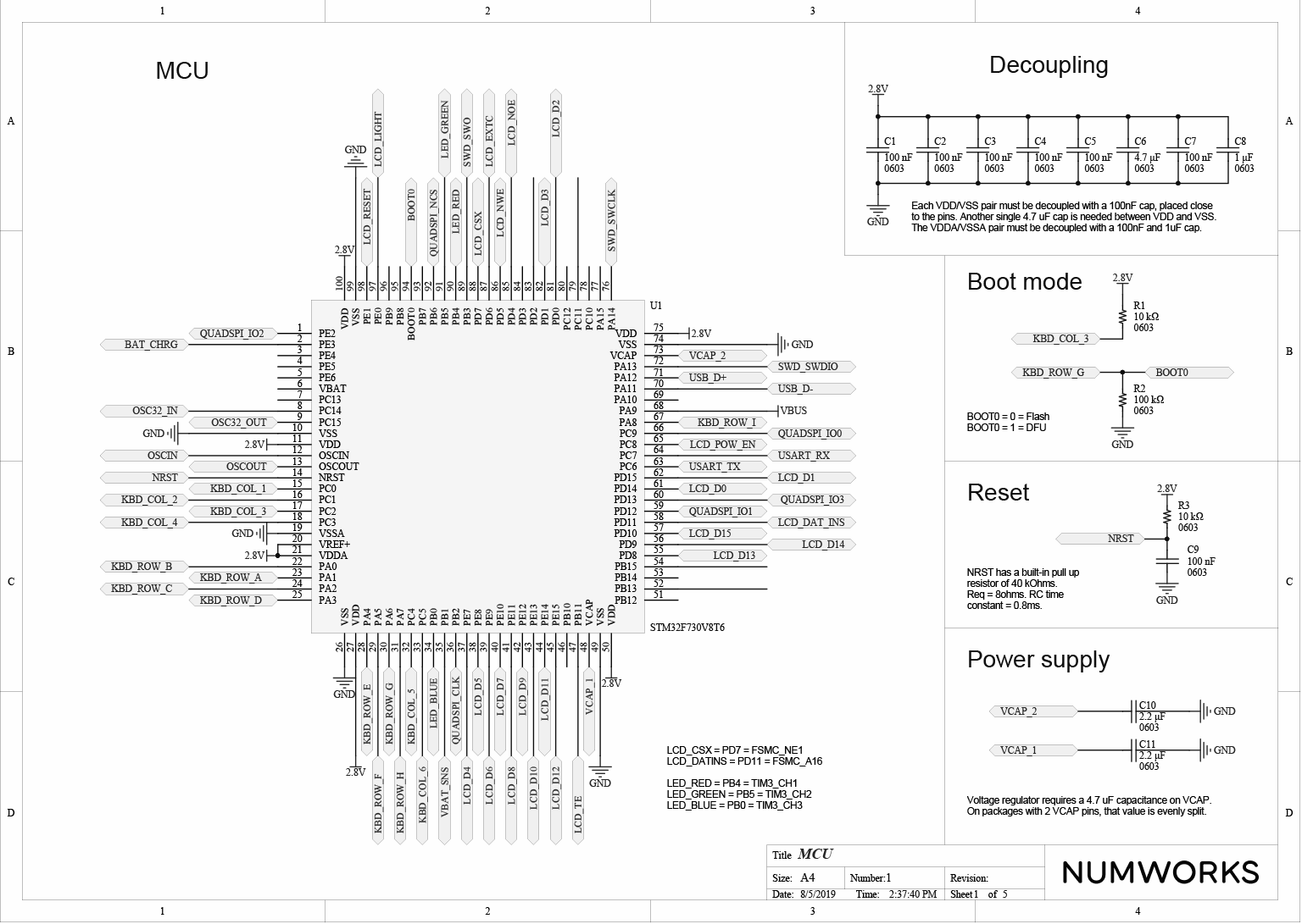
The STM32F730 is the centerpiece of our calculator. It's interfacing with pretty much all the other parts of the device. For proper operation, it needs 10 decoupling capacitors. We also added a pull-up on the NRST pin to make sure the device doesn't reboot accidentally.
Oscillator and BOOT0
We are using an external high-speed 8 MHz oscillator. This is not required for untethered operation, but is mandatory when you want to do USB communications.
Last but not least, we tied the BOOT0 pin to VDD through the G3 key. In practice, this makes the device boot in DFU mode when it's reset with the 6 key pressed.
User interface
Keyboard
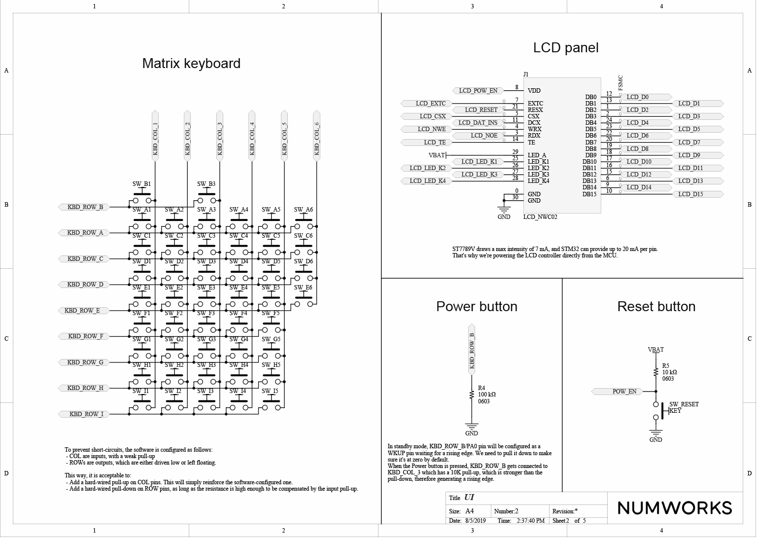
We're using a very usual matrix keyboard layout. This has several implications :
- If 3 keys of a given quad are pressed, we cannot tell whether the fourth one is pressed as well
- No resistor, so we need to be careful when driving the keyboard.
Screen
The screen is interfaced with a 16-bit parallel bus. Since the bus write cycle should be at least 66ns, that allows for a 200fps max theoretical refresh rate.
Peripherals
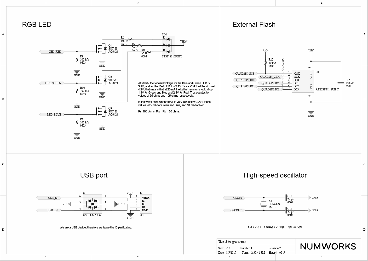
RGB LED
We're powering the LED from the battery. We couldn't drive it from the MCU because it draws too much current, and has a forward voltage that is too high.
We're not bothering with a dedicated regulator ; instead we're using ballast resistors. This is a bit less efficient but a lot simpler.
Reset button
The Reset button virtually disconnects the power to the device.
Power
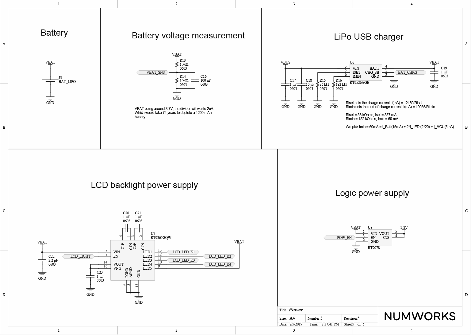
Battery voltage measurement
We're using a very simple divider bridge. What's rather unique here is that the impedance is very high : we need to use very strong resistors (1 MOhm), otherwise too much current would be drained when the device is off. Fortunately, we don't need very high sampling speed, so this simple design works well.
Backlight power supply
To power the backlight of the device we use an IC with a dual-mode charge pump mechanism. This allows for a small package that only requires external capacitors while still keeping a really good efficiency.