
Hélène Pilkiewicz — December 20, 2017
What are those lines on products made out of plastic?
In our previous article on injection molding we saw how a mold works: two halves are pulled away from one another once the plastic has been injected and the newly created plastic part is ejected.
A demoldable part
For this process to work, we need to be able to take the part out of the mold. When this is possible, we say that the part is demoldable. Making a part demoldable is a priority for engineers when they design.
There are a few things to take into account when designing a demoldable part. The first and most important one is shape. We have to be able to choose a limit between the two halves of the mold that allows the mold to open and the part to be ejected.
The parting line
We call that limit between the two mold halves the parting line or parting plan.
For the back cover, the mold opens in the same direction as the thickness of the part. In the video above, the parting line is horizontal.
How to choose the parting line?
There is an infinity of horizontal plans that cut through the part. We have to chose one that allows for easy removal of the part from the mold halves - it always comes back to this!
You might start to wonder how we know what makes a part demoldable given a parting line. So let’s start with a first example, so you can understand what a problematic situation looks like.
The picture below is a sectional view of the mold. You can see the back cover in the middle.
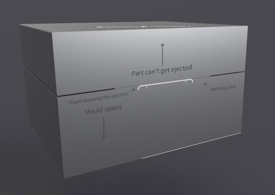
With this parting line, we can open the mold, but we cannot remove the part from the bottom part of the mold: the rounded shape on the side would be stuck in the mold. So we need to pick another parting line!
The parting line we chose is shown in the sectional view below.

With this parting line, there is no surface that stops the mold from opening. No feature of the mold prevents the part from being ejected out of the bottom half. The back cover is therefore demoldable with this simple two-halves mold.
What we can learn from this example is that in most cases, especially if the part is simple, the parting line is placed where the part is the widest. It is the easiest way to ensure that you can take the part out of the mold.
Lines on plastic products
In real life, the contact between the two halves of the mold is never perfect and the parting line leaves a small mark on the injected parts. We can easily see it on toys, figurines..
On the back cover for example it is almost impossible to see it. But if you look at the side of the cover, you will see a tiny bump running through the side of the part: that is the parting line!
Complex parts
From time to time, it is impossible to find an opening direction and a parting line that would allow us to use a simple mold. In that case, we have to alter the shape of the part. And if the design can not be changed, we need to use a more complex mold.
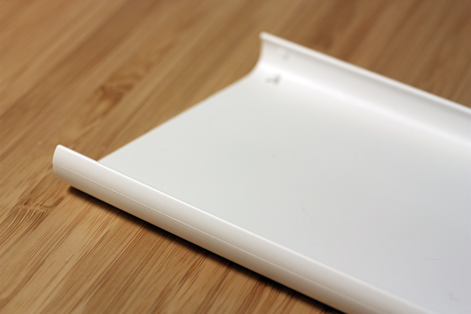
If you look at the picture of the protective cover above, the line on the side shows that the parting line is horizontal and that the mold’s opening direction is vertical. With this solution, the inside of the cover would block the motion of a simple, two-halves mold. Because the jaw-like feature is the whole essence of this part, we had to use a more complex mold which we will detail in a future article.
Hélène Pilkiewicz — Industrial Engineer
Hélène is the creator of all the physical aspects of the NumWorks graphing calculator. She joined our team in September 2016 as an Industrial Engineer. Hélène has a Master's in Industrial Engineering. She works on everything involved with producing the calculator: design of plastic parts, choice of suppliers and monitoring of production and quality. Every time you use your calculator, you are touching Hélène's masterpiece! When not tinkering in her workshop, Hélène is finding new and interesting ways to eat her favorite food: broccoli!